Arc Blast – Part Two
By Andrew Hall
In “Arc Blast – Part One” we looked at how arc blast from current in the atmosphere could produce supersonic shock and wind effects that create a mountain. We examined triangular buttresses on mountainsides that exhibit the characteristic standing wave-form of a reflected shock wave. In particular, we looked at how they are layered perpendicular to the wind direction, and exhibit compression and expansion from superimposed longitudinal and transverse waves that came from a source above.
We now examine more, compelling evidence.
Harmonics . . .
The images below are color enhanced Schlieren photographs of reflected shock waves in a wind tunnel.
Wind tunnels typically show supersonic flow between two surfaces. The initial shock reflects from both walls, creating two triangular wave-forms adjacent to each other. The diamond patterns that form between the triangles are often called ‘shock diamonds’.
In the case where a supersonic shock wave is created in the air, it is unbounded above, so the only surface reflecting it is the ground, and it creates a row of triangles instead of two opposing rows.
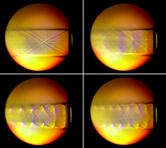 The initial wind speed in the first frame (top left) is Mach 2. It shows the shock wave producing one and a half diamonds.
The wind tunnel is charged with gas in a pressure vessel. So, as the gas flow progresses, the pressure and mass flow decrease from the pressure vessel, lowering the Mach speed of the wind.
The subsequent frames shows instability in the shock waves as the winds slow. The wave-forms compress and the angles of the primary and reflected waves grow less acute.
Vertical shock waves form, called normal shocks, which travel through the triangles, distorting their shape where the normal wave crosses the reflected wave, causing more reflections. New smaller triangles form and replace the original standing wave. This is harmonic reflection of the primary shock wave.
In the final frame (bottom, right) the wind speed has slowed, the triangular wave-forms are smaller and higher frequency. There are seven shock diamonds where there were initially one and one half.
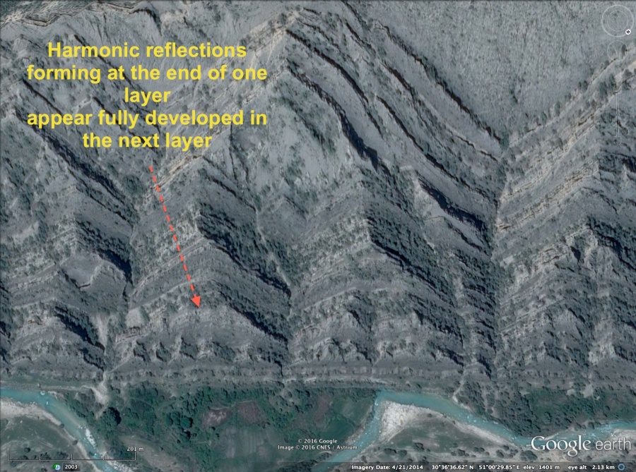
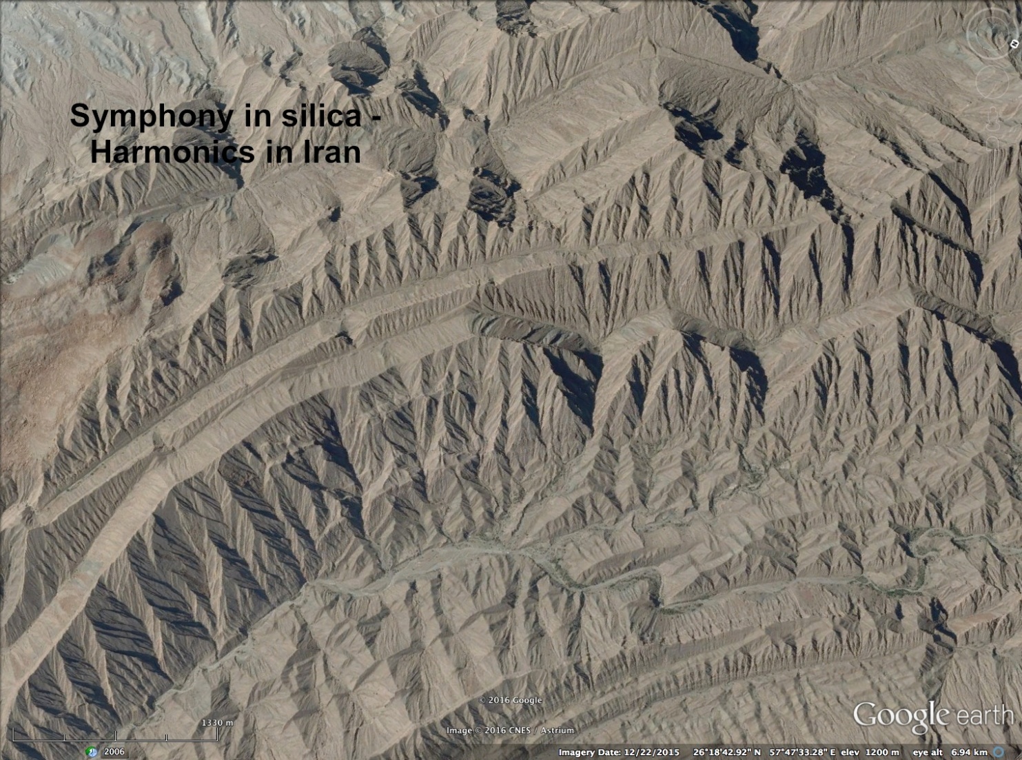
This sequence of harmonic reflection as the energy of the shock wave dissipates is evident on the triangular buttresses stacked on the sides of mountains. As seen in the images below, triangles are stacked upon triangles in harmonic multiples as the successive layers of material were deposited by supersonic winds, tunneled by the reflected shock waves.
The first image in this group is most instructive. In it, the lower-most layers of harmonic waveform can be seen to have begun to form at the outer edge of the preceding layer.

Instability, Interference and Cancellation . . .
 Transients in wind speed, Mach angle and multiple reflections create instabilities in the wave-forms. Unstable waves segregate and fan away from each other under expansion, fragmenting the wave-forms.
Or they bunch together in compression, pressing waves against each other. Shock waves don’t cross, but fold against each other, like magnetic fields interfering.
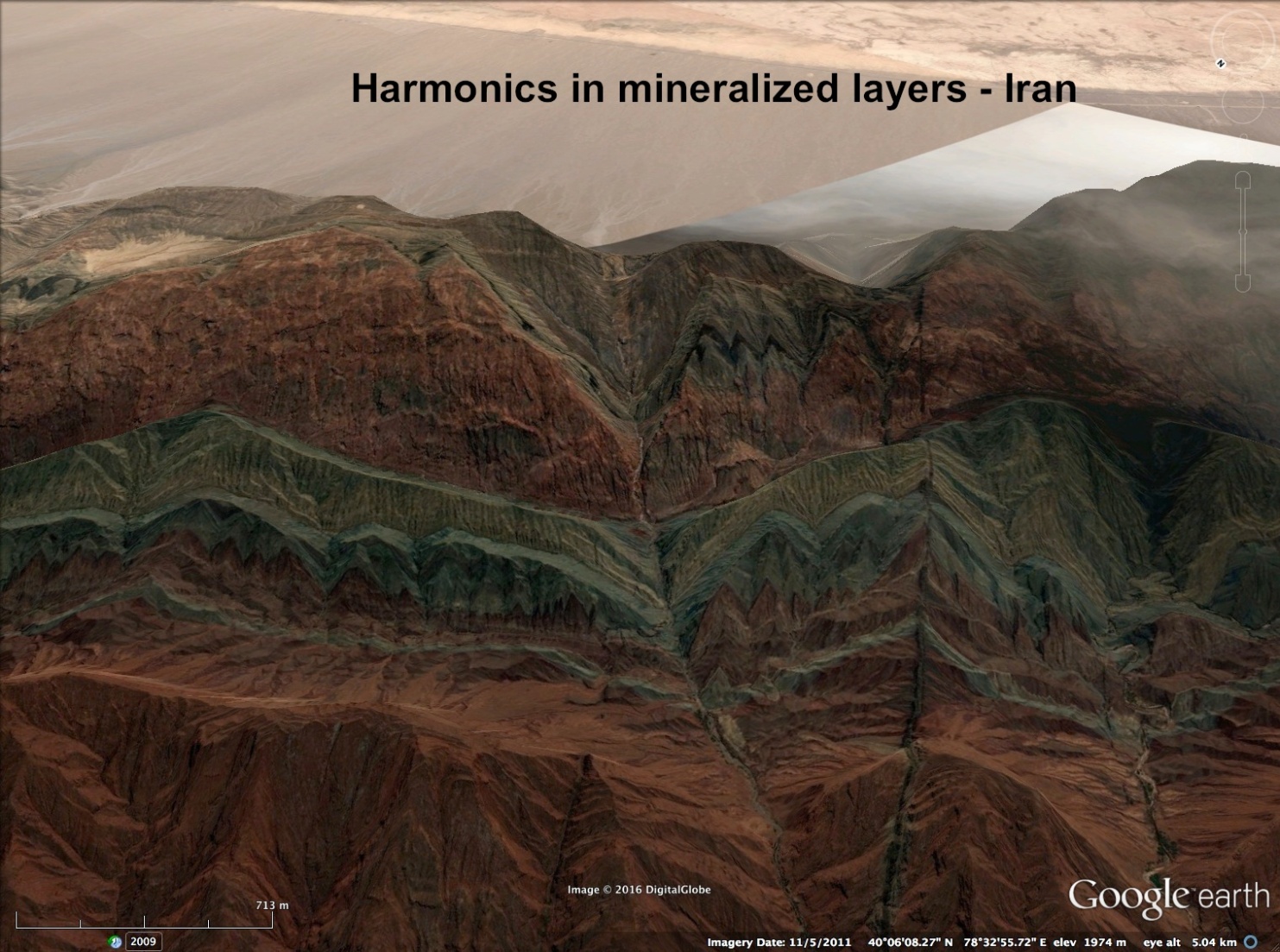
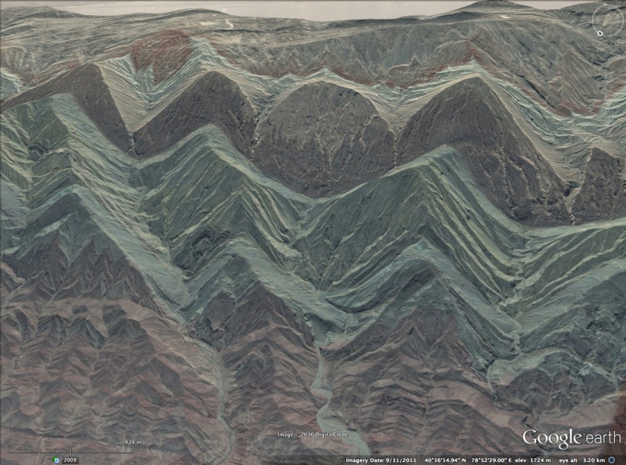
As wave-fronts compress, the wave-form can be squeezed and cancelled-out. In this image of a mountain in Iran, three wave-forms compress, distorting into curves where the waves, pressed against each other, bend the center wave-form almost circular. In the following layers, the pinched wave has cancelled altogether and the surrounding wave-forms have joined, stretching wavelengths to close the gap.
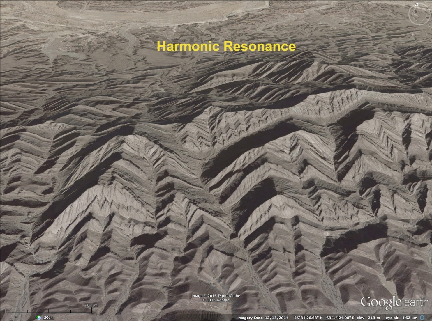
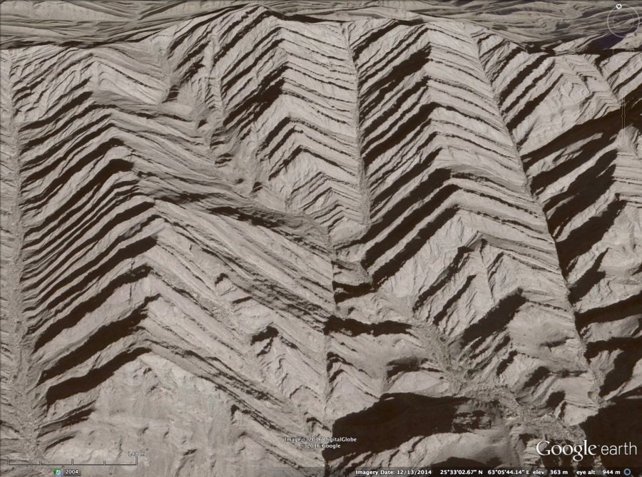
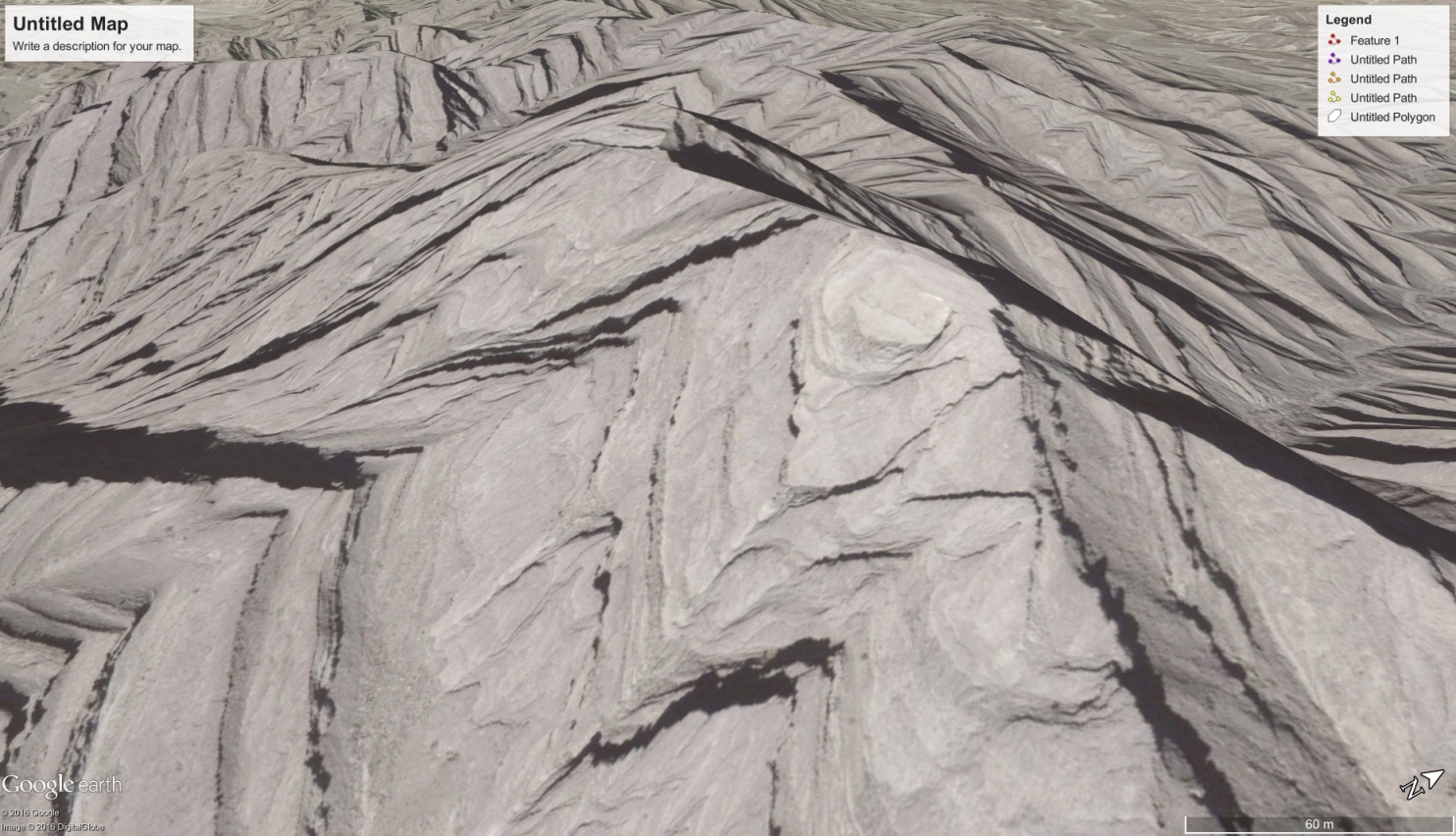
 A similar wave cancellation has occurred in the next image. Here the center wave-form is cancelled by neighboring wave-forms, and they have expanded to fill the wavelength. A diagonal shock line appears cutting the mountain where the cancellation occurs. It crosses in a step-wise fashion, a few layers at a time, causing it to zig-zag. Note the ruler straight shock lines that divide the adjacent triangular buttresses.
Complex Wave-forms . . .
Complexity is found within the shock fronts, inside the triangles themselves, as pressure and density variations.

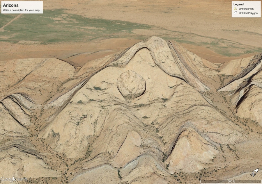
Note the density variations form a circular feature near the top of this Schlieren image. The same feature is on the distorted triangular buttress found in Northern Arizona, shown below.
Also, note how the edges of the triangle draw in towards the circle, just as the waves near the top in the Schlieren image do. The three small buttresses below the hole show a striking similarity to the size and location as those on the wave-forms in the same position in the Schlieren image.
 Here is another hole created in a triangular buttress. This one is in Iran.
The Lambda Foot . . .
This road cut is in Iran and is sometimes described as the slip fault that created the ‘horst-graben’ or basin and range region where this is found.
That isn’t the case. This slice in the ground was left by the primary, or incident shock (left side of the ‘V’) and its reflected shock (right side of the ‘V’).
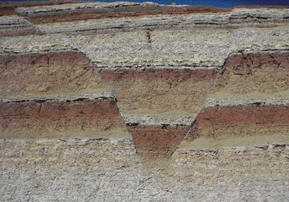
This is the boundary region where the initial shock meets and reflects from the ground. The incident shock curves sharply downward, and the reflected shock is nearly straight. Where the reflected shock and incident shock meet, there is a feature called the lambda foot.
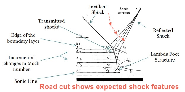
Note, the incident shock curvature and the particular dip of the sedimentary layers within the ‘V’. They are similar to the angled transmitted shocks shown in the ‘V’ of the diagram. Here is another image with a broader view. In this view, the lambda foot is easier to discern.

Also, a feature not originally shown on the diagram, the cut in the center top of the ‘V’ results from a shock that curves downward, normal to the expanding corner of the reflected shock, annotated in red on the “road cut” diagram.
This shock feature is along the side of a hill that can be seen stacking in layers to the left. It should define the outer boundary of the initial shock wave. If so, it should form a ring around the mountain. A similar ‘V’ shaped cut should be found on the opposite side of the hill. If true, the incidence angles, and distance between this ‘V’ and the predicted ‘V’ on the opposite side, hold information about the height of the apex of the passing wave.
Conclusions . . .
Harmonic repetition is undeniably evident on triangular buttresses — proof they resulted from a sonic shock event. It is proof they were created in a single, coherent event, and could not possibly be the result of time and erosion.
The other effects examined are particular to sonic shock waves as well. In Part Three, evidence for electromagnetic effects of the arc blast will be reviewed.
Additional Resources:
Surface Conductive Faults | Thunderblog
Arc Blast — Part One | Thunderblog
YouTube Playlists through 4-2022:
Andrew Hall — EU Geology and Weather
Andrew Hall — Eye of the Storm Episodes (13)
Andrew Hall is an engineer and writer, who spent thirty years in the energy industry. He was a speaker at the EU2016 conference and can be reached at hallad1257@gmail.com or https://andrewdhall.wordpress.com/
Disclosure: The proposed theory of arc flash and arc blast and their effects on the landscape are the sole ideas of the author, as a result of observation, experience in shock and hydrodynamic effects, and deductive reasoning. Dr. Mark Boslough’s simulation of an air burst meteor provided significant insight into the mechanism of a shock wave. His simulation can be viewed on YouTube: Mark Boslough. The author makes no claims that this method is the only way mountains or other geological features are created.
The ideas expressed in Thunderblogs do not necessarily express the views of T-Bolts Group Inc or The Thunderbolts ProjectTM.